


Beam strengthening
CFRP laminate and CFRP sheets
The final scheme is that all the beams of the building are strengthened by carbon fiber reinforced polymer(CFRP) laminates, and the inclined section is strengthened by carbon fiber reinforced polymer(CFRP) sheets.

Project
Because of the renewal of production equipment, the living load of floor and equipment load increase, the original bearing capacity of the industrial building is insufficient, so it is necessary to inspect and reinforce the lower bearing components, and the construction period is very tight, and the construction conditions are poor.
Combined with the concrete appraisal of the project, on the basis of meeting the wishes of Party A, CFRP is used to reinforce the F 2 floor beam. However, in the process of further testing and accounting, it is found that the bearing capacity of most of the beams in this building is quite different, and the number of storeys needed for strengthening with more layers CFRP sheets. The final scheme is that all the beams of the building are strengthened by carbon fiber laminates, and the inclined section is strengthened by carbon fiber fabric. The design and construction of the project progressed smoothly, and the reinforcement beams were sampled 7 days after the completion of the construction. The in-situ surcharge test was carried out under the applied load, and no abnormality was found. At present, the project has been put into operation for half a year and is in good use.
Reinforcement survey and properties of CFRP laminate and CFRP sheet
The building is a frame structure, the reinforcement storey column spacing is 6 m, the area is about 1100 m 2. The number of primary and secondary beams is many: the original design of the concrete strength grade is c25, the stress bar is grade II. Before reinforcement, the concrete strength grade of reinforced concrete beams was tested comprehensively, which was lower than C25. C20 was used in reinforcement design. The bearing capacity of all the beams in the plane is checked by using the reinforcement quantity provided by the original juice drawing. There are 45 beams to be strengthened and 29 beams to be strengthened.
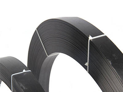
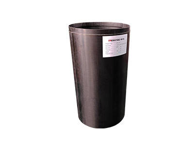
1.2mm carbon fiber laminate
![]()
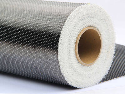
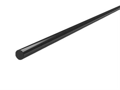
230g carbon fiber fabric
Key points of CFRP laminate and sheet reinforcement construction
The construction technology of CFRP reinforcement is relatively simple, but the construction process is more stringent and the quality of construction personnel is higher. Only by ensuring the construction quality halo can the expected reinforcement effect be achieved.
The main steps are:
concrete surface treatment;
leveling treatment;
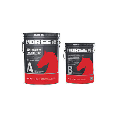
brushing the underlying resin;
pasting carbon fiber laminate;
protection treatment;
There are two points for special attention in actual construction.
(1) the interface must be well handled, otherwise it will directly affect the bond strength. The surface of concrete should be polished carefully with special tools, cleaned with acetone, and the corners of the stickers should be strictly compacted into arcs, and treated smoothly with materials.
(2) when the CFRP is attached, the plates must be scrubbed clean and the binder should be evenly brushed. When pasted, use special roller to roll back and forth to ensure that there is no drum. In addition, the project is an industrial building with a maximum temperature of 60 C and a 2.5mm thick protective layer of M5 mortar mixed with glue on the surface of carbon fiber.
Inspection and acceptance
In order to ensure the safety and reliability of the engineering structure, the inspection and acceptance criteria are strictly checked. In addition to the on-site monitoring during the whole construction process, the mechanical properties of the reinforcement materials were tested and a typical reinforcement beam LL 2 was selected 7 days after the completion of the reinforcement.
Considering the complexity of force transfer between the main beam and the secondary beam, it is not easy to analyze the force. The L-2 beam we selected is a secondary beam in three parts of the plate with 21 axis, 22 axis and A axis and 1/B axis surrounded by 6 m *6 M. The load is transmitted directly from the plate surface.
The length of the tested beam is 6m, the bearing area is 12m2, the floor live load is 7kn/m2, the local equipment load is 117kn in the middle of the beam, and the total load is 201kN. Loading is carried out on site stacking, adding l0kN at each level, simulating the actual distribution of load and stacking the bag. The strain along the height and the load f(0.01mm)~deflection relationship of the middle section of the girder span are measured under each level of load. The variation of the beam and the development of cracks are observed. When loading to 180kn, tiny cracks were observed with the crack observation instrument, which was not visible to the naked eye. No significant changes were observed when loading to 201kN. There is a straight line relationship between load and deflection in the whole loading process. When loaded to 20 1kN, the deflection measured is much less than the allowable deflection of the beam. The five strain gauges attached to the beam height have been intact. The strain diagram drawn under each load basically conforms to the strain law of plane section, which shows that the carbon fiber laminate and concrete work together and the interface between them is well bonded.


